What is an STL file? What is it good for? How does it work? We simply explain the STL file format for 3D printing in depth.
Here’s a primer on what they are and how they work, the advantages and disadvantages of their use, plus alternative file formats to consider. In this article, we’re talking about the 3D printing file format, not about the Standard Template Library in C++.
STL File Format (3D Printing) – Simply Explained
- What is an STL File?
- What does the file extension .STL stand for?
- How does the STL file format store a 3D model?
- How does an STL file store information about facets?
- Special rules for the STL format
- How is an STL file 3D printed?
- Is Every STL File 3D Printable?
- Optimizing an STL file for best 3D printing performance
- Are there any alternatives to the STL File Format?
- Advantages and disadvantages of using STL file format over other file formats
- Color in STL File Format
- STL file resources
1. What is an STL File?
In a nutshell, an STL file stores information about 3D models. This format describes only the surface geometry of a three-dimensional object without any representation of color, texture or other common model attributes.
These files are usually generated by a computer-aided design (CAD) program, as an end product of the 3D modeling process. “.STL” is the file extension of the STL file format.
The STL file format is the most commonly used file format for 3D printing. When used in conjunction with a 3D slicer, it allows a computer to communicate with 3D printer hardware.
Since its humble beginnings, the STL file format has been adopted and supported by many other CAD software packages, and today is widely used for rapid prototyping, 3D printing, and computer-aided manufacturing. Hobbyists and professionals use it alike.
2. What does the file extension .STL stand for?
The true meaning of the file extension .STL has been lost to the mists of time.
It’s widely believed to be an abbreviation of the word STereoLithography, though sometimes it is also referred to as “Standard Triangle Language” or “Standard Tessellation Language”.
3. How does the STL file format store a 3D model?
The main purpose of the STL file format is to encode the surface geometry of a 3D object. It encodes this information using a simple concept called “tessellation”.
3.1 Tessellation
Tessellation is the process of tiling a surface with one or more geometric shapes such that there are no overlaps or gaps. If you have ever seen a tiled floor or wall, that is a good real life example of tessellation.

Tessellation can involve simple geometric shapes or very complicated (and imaginative) shapes. Here are some examples of artistic tessellations due to the famous painter M. C. Escher. In fact, if you want to see more examples of amazing tessellations, we recommend that you check out his paintings.

3.2 The invention of the STL file format: exploiting tessellation to encode surface geometry
Back in 1987, Chuck Hull had just invented the first stereolithographic 3D printer, and The Albert Consulting Group for 3D Systems were trying to figure out a way to transfer information about 3D CAD models to the 3D printer. They realized that they could use tessellations of the 3D model’s surface to encode this information!

The basic idea was to tessellate the 2 dimensional outer surface of 3D models using tiny triangles (also called “facets”) and store information about the facets in a file.
Let’s look at a few examples to understand how this works. For example, if you have a simple 3D cube, this can be covered by 12 triangles, as shown in the image below. As you can see, there are two triangles per face. Since the cube has six faces, it adds up to 12 triangles.
If you have a 3D model of a sphere, then it can be covered by many small triangles, also shown in the same image.
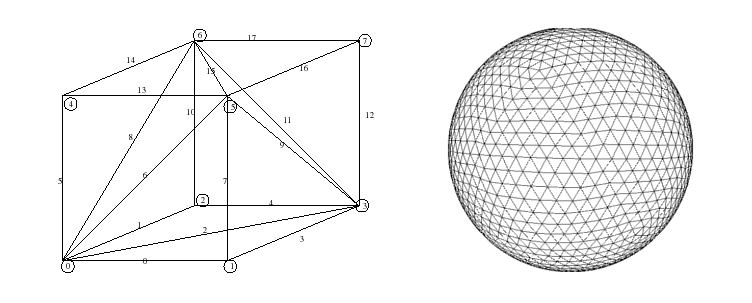
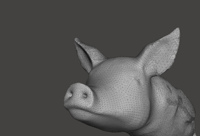
Here is another example of a very complicated 3D shape which has been tessellated with triangles.
The Albert Consulting Group for 3D Systems realized that if they could store the information about these tiny triangles in a file, then this file could completely describe the surface of an arbitrary 3D model. This formed the basic idea behind the STL file format!
4. How does an STL file store information about facets?
The STL file format provides two different ways of storing information about the triangular facets that tile the object surface. These are called the ASCII encoding and the binary encoding. In both formats, the following information of each triangle is stored:
- The coordinates of the vertices.
- The components of the unit normal vector to the triangle. The normal vector should point outwards with respect to the 3D model.

4.1 The ASCII STL file format
The ASCII STL file starts with the mandatory line:
where is the name of the 3D model. Name can be left blank, but there must be a space after the word solid in that case.
The file continues with information about the covering triangles. Information about the vertices and the normal vector is represented as follows:
Here, n is the normal to the triangle and v1, v2 and v3 are the vertices of the triangle. Co-ordinate values are represented as a floating point number with sign-mantissa-e-sign-exponent format, e.g., “3.245000e-002”.
The file ends with the mandatory line:
4.2 The binary STL file format
If the tessellation involves many small triangles, the ASCII STL file can become huge. This is why a more compact binary version exists.
The binary STL file starts with a 80 character header. This is generally ignored by most STL file readers, with some notable exceptions that we will talk about later. After the header, the total number of triangles is indicated using a 4 byte unsigned integer.
The information about the triangles follow subsequently. The file simply ends after the last triangle.
Each triangle is represented by twelve 32-bit floating point number. Just like the ASCII STL file, 3 numbers are for the 3D Cartesian co-ordinates of the normal to the triangle. The remaining 9 numbers are for the coordinates of the vertices (three each). Here’s how this looks like:
Note that after each triangle, there is a 2 byte sequence called the “attribute byte count”. In most cases, this is set to zero and acts a spacer between two triangles. But some software also use these 2 bytes to encode additional information about the triangle. We will see such an example later, where these bytes will be used to store color information.
5. Special rules for the STL format
The STL specification has some special rules for tessellation and for storing information.
5.1 The vertex rule
This rule is to be respected when tessellating the surface of the 3D object.
Here’s an example of a valid and invalid tessellation, according to this rule. The figure on the left violates this rule and is an invalid tessellation, while the figure on the right is conformant and a valid tessellation.

5.2 The orientation rule
First, the direction of the normal should point outwards. Second, the vertices are listed in counterclockwise order when looking at the object from the outside (right-hand rule).

This redundancy exists for a reason. It helps ensure consistency of the data and spot corrupt data. A software can, for example, calculate the orientation from the normal and subsequently from the vertices and verify whether they match. If it doesn’t, then it can declare the STL file to be corrupt!
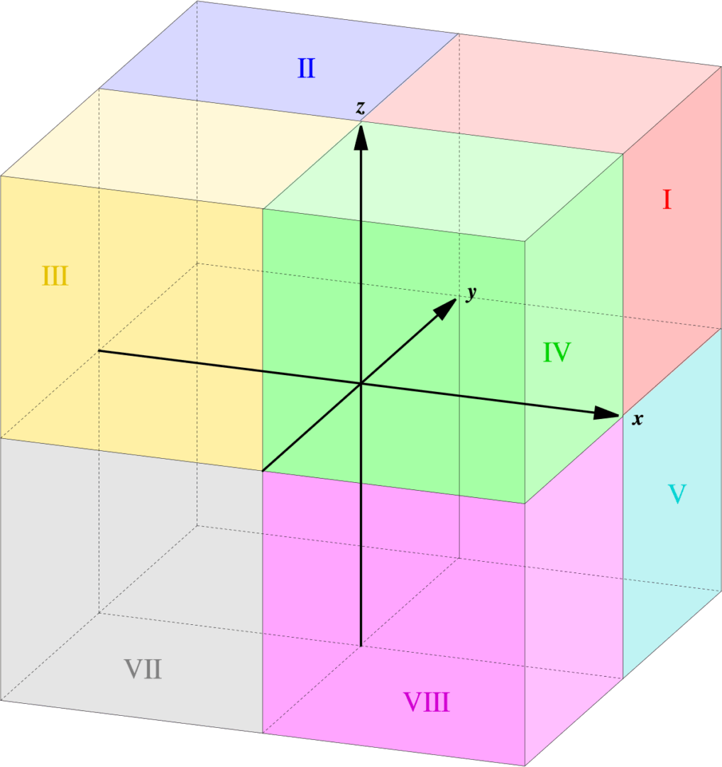
5.3 The all positive octant rule
This implies that the 3D object lives in the all-positive octant of the 3D Cartesian coordinate system (and hence the name).
The rationale behind this rule is to save space. If the 3D object was allowed to live anywhere in the coordinate space, we would have to deal with negative co-ordinates. To store negative co-ordinates, one needs to use signed floating point numbers. Signed floating point numbers require one additional bit to store the sign (+/-). By ensuring that all coordinates are positive, this rule makes sure that we are able to use unsigned numbers for the coordinates and save a bit for every coordinate value we store.
5.4 The triangle sorting rule
This helps Slicers slice the 3D models faster. However, this rule is not strictly enforced.
6. How is an STL file 3D printed?
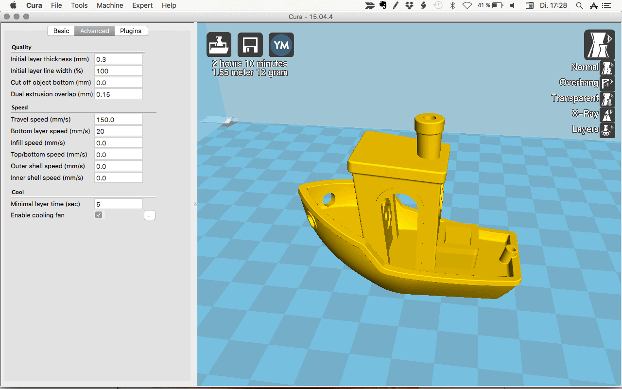
For 3D printing, the STL file has to be opened in a dedicated slicer. What’s a slicer? It’s a piece of 3D printing software that converts digital 3D models into printing instructions for your 3D printer to create an object.
The slicer chops up your STL file into hundreds (sometimes thousands) of flat horizontal layers based on the settings you choose and calculates how much material your printer will need to extrude and how long it will take to do it.
All of this information is then bundled up into a GCode file, the native language of your 3D printer. Slicer settings do have an impact the quality of your print so it’s important to have the right software and settings to get you the best quality print possible.
Once the GCode has been uploaded to your 3D printer, the next stage is for those separate two-dimensional layers to be reassembled as a three-dimensional object on your print-bed. This is done by depositing a succession of thin layers of plastics, metals, or composite materials, and building up the model one layer at a time.
More information: 3D Slicer Settings for Beginners – 8 Things You Need to Know
7. Is Every STL File 3D Printable?

Unfortunately not. Only a 3D design that’s specifically made for 3D printing is 3D printable. The STL file is just the container for the data, not a guarantee that something is printable.
3D models suitable for 3D printing need to have a minimum wall thickness and a “watertight” surface geometry to be 3D printable. Even if it’s visible on a computer screen, it’s impossible to print something with a wall thickness of zero.
There’s also the consideration of overhanging elements on the model. Look at the ALL3DP logo in the picture above; if the model is printed upright, then overhanging elements with more than a 45-degree angle will require supports (which you can see in green).
When downloading an STL file that you haven’t created yourself, it’s worth taking the time to verify that it is indeed 3D printable. This will save you a lot of time and frustration (and wasted filament).
Further reading: MeshMixer Tutorial for 3D Printing Beginners and 9 Important 3D Printing Concepts Everyone Should Know
8. Optimizing an STL file for best 3D printing performance
The STL file format approximates the surface of a CAD model with triangles. The approximation is never perfect, and the facets introduce coarseness to the model.

The 3D printer will print the object with the same coarseness as specified by the STL file. Of course, by making the triangles smaller and smaller, the approximation can be made better and better, resulting in good quality prints. However, as you decrease the size of the triangle, the number of triangles needed to cover the surface also increases. This leads to gigantic STL file which 3D printers cannot handle. It’s also a pain to share or upload huge files like that.
It is therefore very important to find the right balance between file size and print quality. It does not make sense to reduce the size of the triangles ad infinitum because at some point your eye is not going to be able to distinguish between the print qualities.
Most CAD software offer a couple of settings when exporting STL files. These settings control the size of the facets, and hence print quality and file size. Let’s dig into the most important settings and find out their optimum values.
8.1 Chord height or tolerance
Most CAD software will let you choose a parameter called chord height or tolerance. The chord height is the maximum distance from the surface of the original design and the STL mesh. If you choose the right tolerance, your prints will look smooth and not pixelated. It’s quite obvious that the smaller the chord height, the more accurately the facets represent the actual surface of the model.

It is recommended to set the tolerance between 0.01 milimeters to 0.001 milimeters. This usually results in good quality prints. There is no point in reducing this any further, as 3D printers cannot print with that level of detail.
8.2 Angular deviation or angular tolerance
Angular tolerance limits the angle between the normals of adjacent triangles. The default angle is usually set at 15 degrees. Decreasing the tolerance (which can range to 0 to 1) improves print resolution.

The recommended setting for this parameter is 0.
8.3 Binary or ASCII?
Finally, you have a choice of exporting the STL file in binary or ASCII format. The binary format is always recommended for 3D printing since it results in smaller file sizes. However, if you want to manually inspect the STL file for debugging, then ASCII is preferable because it is easier to read.
9. Are there any alternatives to the STL File Format?

The STL file format is not the only format used in 3D printing. There are over 30 file formats for 3D printing. Most important is the OBJ file format, which can store color and texture profiles. Another option the is Polygon file format (PLY), which was originally used for storing 3D scanned objects.
More recently, there have been efforts to launch a new file type by The 3MF Consortium, which is proposing a new 3D printing file format called 3MF. They claim it will streamline and improve the 3D printing process.
To implement it, Microsoft has partnered up companies like Autodesk, HP, and Shapeways to make their vision a reality. More details on the 3MF Consortium can be read on their website, together with preliminary documentation about the 3MF file type on their GitHub page. It’s far too early to say whether this will become widely adopted, however.
10. Advantages and disadvantages of using STL file format over other file formats
Since there are many 3D printing file formats, the obvious question is : which one should you use for your prints? The answer, as it turns out, depends a lot on your use case.
10.1 When not to use an STL file
As we saw earlier, the STL file format cannot store additional information such as color, material etc. of the facets or triangles. It only stores information about the vertices and the normal vector. This means that if you want to use multiple colors or multiple materials for your prints, then the STL file format is not the right choice. The OBJ format is a popular format enjoying good support which has a way to specify color, material etc. Therefore, this is the right choice for this task.
10.2 When to use an STL file
On the other hand, if you want to print with a single color or material, which is most often the case, then STL is better than OBJ since it is simpler, leading to smaller file sizes and faster processing.
10.3 Other advantages of the STL file format
Universal: Another big advantage of the STL file format is that it is universal and supported by nearly all 3D printers. This cannot be said for the OBJ format, even though it enjoys reasonable adoption and support as well. The VRML, AMF and 3MF formats are not widely supported at this point of time.
Mature ecosystem: Most 3D printable models you can find on the internet are in the STL file format. The existence of this ecosystem, combined with STL-based software investments made by 3D printer manufacturers, has given rise to a large user-base that’s heavily invested in the format. This means there’s plenty of third party software dealing with STL files, which is not the case with the other file formats.
10.4 Some disadvantages of the STL file format
There are some glaring disadvantages to using STL as well. As the fidelity of printing processes embraces micron-scale resolution, the number of triangles required to describe smooth curved surfaces can result in massive file sizes. It’s also impossible to include metadata (such as authorship and copyright information) in an STL file.
10.5 Verdict
If your 3D printing needs are simple, then perhaps there is no reason to move away from the STL file format. However, for more advanced prints using multiple material and color, it is perhaps advisable to try the OBJ or other available formats.
11. Color in STL File Format

In the last section, we said that the STL file format cannot handle multi-color models. The reason the STL file format lacks color information is simple. When rapid prototyping evolved in the 1980s, no one thought of color printing. Nowadays, 3D printing materials and processes have evolved rapidly. Some allow you to print in full-color – just think of sandstone 3D selfies, as pictured above.
However it’s not completely fair to say that STL cannot handle colors. It turns out that there are non-standard versions of the STL format that are indeed capable of carrying color information.
For example, the VisCAM and Solidview software packages use the “attribute byte count” at the end of every triangle to store a 15-bit RGB color using the following system:
- bits 0 to 4 for blue (0 to 31),
- bits 5 to 9 for green (0 to 31),
- bits 10 to 14 for red (0 to 31),
- bit 15 is 1 if the color is valid, or 0 if the color is not valid (as with normal STL files).
The Materialize Magics software, on the other hand, uses the 80-byte header in the binary format to represent the overall color of the 3D object. The color is specified by including the ASCII string “COLOR=” followed by four bytes representing red, green, blue and alpha channel (transparency) in the range 0–255. This base color can also be overridden at each facet using the “attribute byte count” bytes.
12. STL file resources
If you have read so far, congratulations! You now know quite a bit about STL and can be undoubtedly called an STL file format expert.
In this final section, we will share some awesome software and resources that you can use for downloading, viewing, editing and repairing STL files.
12.1 Downloading STL files

There are many repositories, marketplaces and search engines on the web containing literally millions of free STL files. You can refer to our regularly updated list — 35 Best Sites for Free STL Files & 3D Printer Models of 2018 — or you can choose one of these models to get started: 50 Cool Things to 3D Print in Summer 2018
12.2 Opening and viewing an STL file

Fortunately, opening an STL file is not too complicated. There are several free STL file viewers for this purpose, which you can either use online or as a desktop application. Refer to our dedicated guide here: 20 Best Free STL File Viewer Tools of 2018
12.3 Editing and converting an STL file

Yes, it is entirely possible to edit an STL file and convert the STL file to another file format. Because the format is open, there is nothing to prevent you from changing the contents of a file. Actually, the process of editing is quite easy. We have a dedicated article on this topic: 7 Free STL Editors + How to Edit and Repair STL Files
12.4 Repairing an STL file

Remember the section where we discussed the rules that STL files must satisfy? For example, adjacent triangles must share two vertices and the right hand rule applied on the vertices should result in the same orientation as the normal vector. If these conditions are violated in an STL file, then it is broken or corrupt.
There are several programs which can help with repairing a broken STL file. For example, Netfabb Basic is a great tool for repairing the most common STL file problems. You find more information on these programs in our article: 24 Best Free 3D Printing Software Tools of 2018
13. Conclusion
In conclusion, we have learned about how the STL file format encodes the layout of 3D models. We discussed how to optimize STL files for the best 3D printing quality. We talked about how the STL file format compares with the other popular 3D printing file format .OBJ and when to use each of these formats. Finally, we shared some resources using which you can download, view, edit and repair STL files.
We hope that an in-depth understanding of the STL file format helps you become a more knowledgeable user of your 3D printer. If you found this article useful, share it with other 3D printing enthusiasts and spread the word. Do you have some questions or remarks? Let us know in the comments below!
Website: LINK