
Games controllers – like keyboards – are very personal things. What works for one person may not work for another. Why, then, should we all use almost identical off-the-shelf controllers? In the latest issue of HackSpace magazine, we take a look at how to use Raspberry Pi Pico to create a controller that’s just right for you.
We’ll use CircuitPython for this as it has excellent support for USB interfaces. The sort of USB devices that we interact with are called human interface devices (HIDs), and there are standard protocols for common HIDs, including keyboards and mice. This is why, for example, you can plug almost any USB keyboard into almost any computer and it will just work, with no need to install drivers.
We’ll be using the Keyboard type, as that works best with the sorts of games that this author likes to play, but you can use exactly the same technique to simulate a mouse or a gamepad.
Before we get onto this, though, let’s take a look at the buttons and how to wire them up.
We’re going to use eight buttons: four for direction, and four as additional ‘action’ buttons. We’ll connect these between an I/O pin and ground. You can use any I/O pin you like. We’re going to use slightly different ones in two different setups, just because they made sense with the physical layout of the hardware. Let’s take a look at the hardware we’re using. Remember, this is just the hardware we want to use. The whole idea of this is to create a setup that’s right for you, so there’s no need to use the same. Think about how you want to interact with your games and take a look at the available input devices and build what you want.

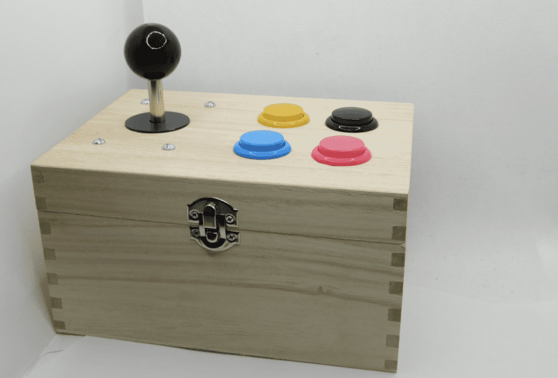
The first setup we’re creating is an Arcade box. This author would really like an arcade machine in his house. However, space limitations mean that this isn’t going to be possible in the near future. The first setup, then, is an attempt to recreate the control setup of an arcade machine, but use it to play games on a laptop rather than a full-sized cabinet.
Arcade controls are quite standard, and you can get them from a range of sources. We used one of Pimoroni’s Arcade Parts sets, which includes a joystick and ten buttons (we only used four of these). The important thing about the joystick you pick is that it’s a button-based joystick and not an analogue one (sometimes called a dual-axis joystick), as the latter won’t work with a keyboard interface. If you want to use an analogue joystick, you’ll need to switch the code around to use a mouse or gamepad as an input device.

As well as the electronics, you’ll need some way of mounting them. We used a wooden craft box. These are available for about £10 from a range of online or bricks and mortar stores. You can use anything that is strong enough to hold the components.
The second setup we’re using is a much simpler button-based system on breadboard-compatible tactile buttons and protoboard. It’s smaller, cheaper, and quicker to put together. The protoboard holds everything together, so there’s nothing extra to add unless you want to. You can personalise it by selecting different-sized buttons, changing the layout, or building a larger chassis around this.
Insert coin to continue
Let’s take a look at the arcade setup first. The joystick has five pins. One is a common ground and the others are up, down, left, and right. When you push the joystick up, a switch closes, linking ground to the up pin. On our joystick the outermost pin is ground, but it’s worth checking on your joystick which pin is which by using a multimeter. Select continuity mode and, if you push the joystick up, you should find a continuous connection between the up pin and ground. A bit of experimentation should confirm which pin is which.
In order to read the pins, we just need to connect the directional output from the joystick to an I/O pin on Pico. We can use one of Pico’s internal pull-up resistors to pull the pin high when the button isn’t pressed. Then, when the button is pressed, it will connect to ground and read low. The joystick should come with a cable that slots onto the joystick. This should have five outputs, and this conveniently slots into the I/O outputs of Pico with a ground on one end.

The buttons, similarly, just need to be connected between ground and an I/O pin. These came with cables that pushed onto the button and plugged into adjacent pins. Since Pico has eight grounds available, there are enough that each button can have its own ground, and you don’t have to mess around joining cables together.
Once all the cables are soldered together, it’s just a case of building the chassis. For this, you need five large holes (one for the joystick and four for the buttons). We didn’t have an appropriately sized drill bit and, given how soft the wood on these boxes is, a large drill bit may have split the wood anyway. Instead, we drilled a 20 mm hole and then used a rotary tool with sanding attachment to enlarge the hole until it was the right size. You have to go quite easy with both the drill and the sanding tool to avoid turning everything into shards of broken wood. Four small holes then allow bolts to keep the joystick in place (we used M5 bolts). The buttons just push into place.

The only remaining thing was a 12 mm hole for a micro USB cable to pass through to Pico. If you don’t have a 12 mm drill bit, two overlapping smaller holes may work if you’re careful.
The buttons just push-fit into place, and that’s everything ready to go.
A smaller approach
Our smaller option used protoboard over the back of Pico. Since we didn’t want to block the BOOTSEL button, we only soldered it over part of Pico. However, before soldering it on at all, we soldered the buttons in place.
Tactile switches typically have four connections. Well, really they have two connections, but each connection has two tabs that fit into the protoboard. This means that you have to orientate them correctly. Again, your multimeter’s continuity function will confirm which pins are connected and which are switched.
Protoboard is a PCB that contains lots and lots of holes and nothing else. You solder your components into the holes and then you have to create connections between them.
We placed the buttons in the protoboard in positions we liked before worrying about the wiring. First, we looked to connect one side of each switch to ground. To minimise the wiring, we did this in two groups. We connected one side of each of the direction buttons together and then linked them to ground. Then we did the same to all the action buttons.
There are two ways of connecting things on protoboard. One is to use jumper wire. This works well if the points are more than a couple of holes apart. For holes that are next to each other, or very close, you can bridge them. On some protoboard (which doesn’t have a solder mask), you might simply be able to drag a blob of solder across with your soldering iron so that it joins both holes. On protoboard with solder mask, this doesn’t work quite so well, so you need to add a little strand of wire in a surface-mount position between the two points and solder it in. If you’ve got a pair of tweezers to hold the wire in place while you solder it, it will be much easier.
For longer connections, you’ll need to use jumper wire. Sometimes you’ll be able to poke it through the protoboard and use the leg to join. Other times you’ll have to surface-mount it. This all sounds a bit complicated, but while it can be a bit fiddly, it’s all fairly straightforward once you put solder to iron.
Program it up
Now that we’ve got the hardware ready, let’s code it up. You’ll first need to load CircuitPython onto your Pico. You can download the latest release from circuitpython.org. Press the BOOTSEL button as you plug Pico into your USB port, and then drag and drop the downloaded UF2 file onto the RP2 USB drive that should appear.
We’ll use Mu to program Pico. If you’ve not used CircuitPython before, it’s probably worth having a quick look through the ’getting started’ guide.
The code to run our games controller is:
import board
import digitalio
import gamepad
import time
import usb_hid
from adafruit_hid.keyboard import Keyboard
from adafruit_hid.keycode import Keycode
kbd = Keyboard(usb_hid.devices)
keycodes = [Keycode.UP_ARROW, Keycode.DOWN_ARROW, Keycode.LEFT_ARROW, Keycode.RIGHT_ARROW, Keycode.X, Keycode.Z, Keycode.SPACE, Keycode.ENTER]
pad = gamepad.GamePad(
digitalio.DigitalInOut(board.GP12),
digitalio.DigitalInOut(board.GP14),
digitalio.DigitalInOut(board.GP9),
digitalio.DigitalInOut(board.GP15),
digitalio.DigitalInOut(board.GP16),
digitalio.DigitalInOut(board.GP17),
digitalio.DigitalInOut(board.GP18),
digitalio.DigitalInOut(board.GP20),
)
last_pressed = 0
while True:
this_pressed = pad.get_pressed()
if (this_pressed != last_pressed):
for i in range(8):
if (this_pressed & 1<<i) and not (last_pressed & 1<<i):
kbd.press(keycodes[i])
if (last_pressed & 1<<i) and not (this_pressed & 1<<i):
kbd.release(keycodes[i])
last_pressed = this_pressed
time.sleep(0.01)
This uses the HID keyboard object (called kbd) to send key press and release events for different key codes depending on what buttons are pressed or released. We’ve used the gamepad module that is for keeping track of up to eight buttons. When you initialise it, it will automatically add pull-up resistors and set the I/O pins to input. Then, it will keep track of what buttons are pressed. When you call get_pressed(), it will return a byte of data where each digit corresponds to an I/O pin. So, the following number (in binary) means that the first and third buttons have been pressed: 00000101. This is a little confusing, because this is the opposite order to how the I/Os are passed when you initialise the GamePad object.
The while loop may look a little unusual as it’s not particularly common to use this sort of binary comparison in Python code, but in essence, it’s just looking at one bit at a time and seeing either: it’s now pressed but wasn’t last time the loop ran (in which case, it’s a new button press and we should send it to the computer), or it isn’t pressed this loop but was the previous loop (in which case, it’s newly released so we can call the release method).
The << operator shifts a value by a number of bits to the left. So, 1<<2 is 100, and 1<<3 is 1000. The & operator is bitwise and so it looks at a binary number and does a logical AND on each bit in turn. Since the right-hand side of the & is all zeros apart from one bit (at a different position depending on the value of i), the result will be dependent on whether the value of this_pressed or last_pressed is 1 or 0 at the position i. When you have an if condition that’s a number, it’s true if the number is anything other than 0. So, (this_pressed & 1<<2) will evaluate to true if there’s a 1 at position 2 in the binary form of this_pressed. In our case, that means if the joystick is pushed left.
You can grab this code from the following link – hsmag.cc/USBKeyboard. Obviously, you will need to update the GPIO values to the correct ones for your setup when you initialise GamePad.
We’ve taken a look at two ways to build a gamepad, but it’s up to you how you want to design yours.
Issue 42 of HackSpace magazine is on sale NOW!

Each month, HackSpace magazine brings you the best projects, tips, tricks and tutorials from the makersphere. You can get it from the Raspberry Pi Press online store or your local newsagents. As always, every issue is free to download from the HackSpace magazine website.
Website: LINK